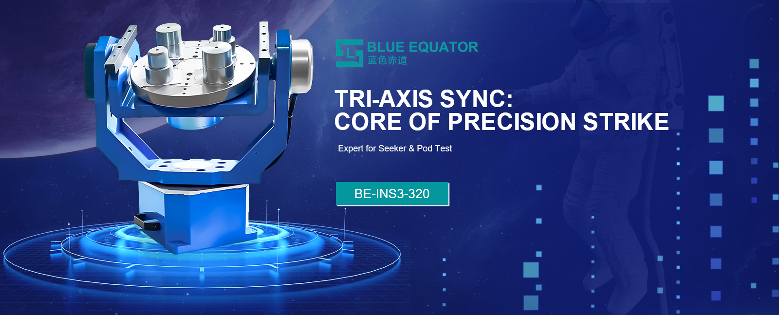
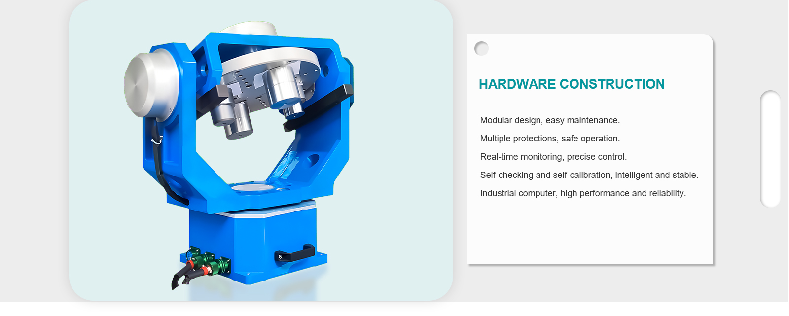
• White background Motion Simulation Rate Table with three-axis angular positioning for inertial navigation system calibration.
  • Motion Simulation Rate Table installed in aerospace lab with integrated sensor arrays.
  • Close-up of Motion Simulation Rate Table precision bearing assembly for ultra-smooth rotation.
  • Motion Simulation Rate Table operating in marine navigation system testing scenario.
  • Motion Simulation Rate Table size comparison showing compact 800mm width design.
  • Motion Simulation Rate Table executing high-speed rotation tests for speed sensor calibration.
  • White background Motion Simulation Rate Table with three-axis angular positioning for inertial navigation system calibration.
  • Motion Simulation Rate Table installed in aerospace lab with integrated sensor arrays.
  • Close-up of Motion Simulation Rate Table precision bearing assembly for ultra-smooth rotation.
  • Motion Simulation Rate Table operating in marine navigation system testing scenario.
  • Motion Simulation Rate Table size comparison showing compact 800mm width design.
  • Motion Simulation Rate Table executing high-speed rotation tests for speed sensor calibration.

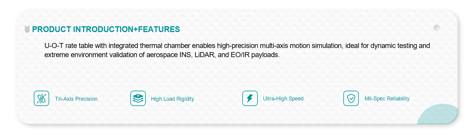
Motion Simulation Rate Table for inertial navigation system calibration and gyroscope testing in aviation automotive and marine applications.

No.BE-INS3-320
The Motion Simulation Rate Table delivers ±0.0005° angular positioning accuracy, supports up to 50kg payload, and offers three-axis motion control. Ideal for inertial navigation system calibration, fiber optic gyroscope testing, and MEMS sensor validation, it ensures exceptional repeatability, stable operation, and precise angular velocity control for aerospace, marine, and industrial R&D projects.
Specifications
Countertop flatness:
≤0.03mm
Angle position repeatability:
≤ 5"
angular rate:
±500°/s
angular acceleration:
300°/S²
Rated load weight:
15kg
Download
View all downloads
  • White background Motion Simulation Rate Table with three-axis angular positioning for inertial navigation system calibration.
  • Motion Simulation Rate Table installed in aerospace lab with integrated sensor arrays.
  • Close-up of Motion Simulation Rate Table precision bearing assembly for ultra-smooth rotation.
  • Motion Simulation Rate Table operating in marine navigation system testing scenario.
  • Motion Simulation Rate Table size comparison showing compact 800mm width design.
  • Motion Simulation Rate Table executing high-speed rotation tests for speed sensor calibration.

Description

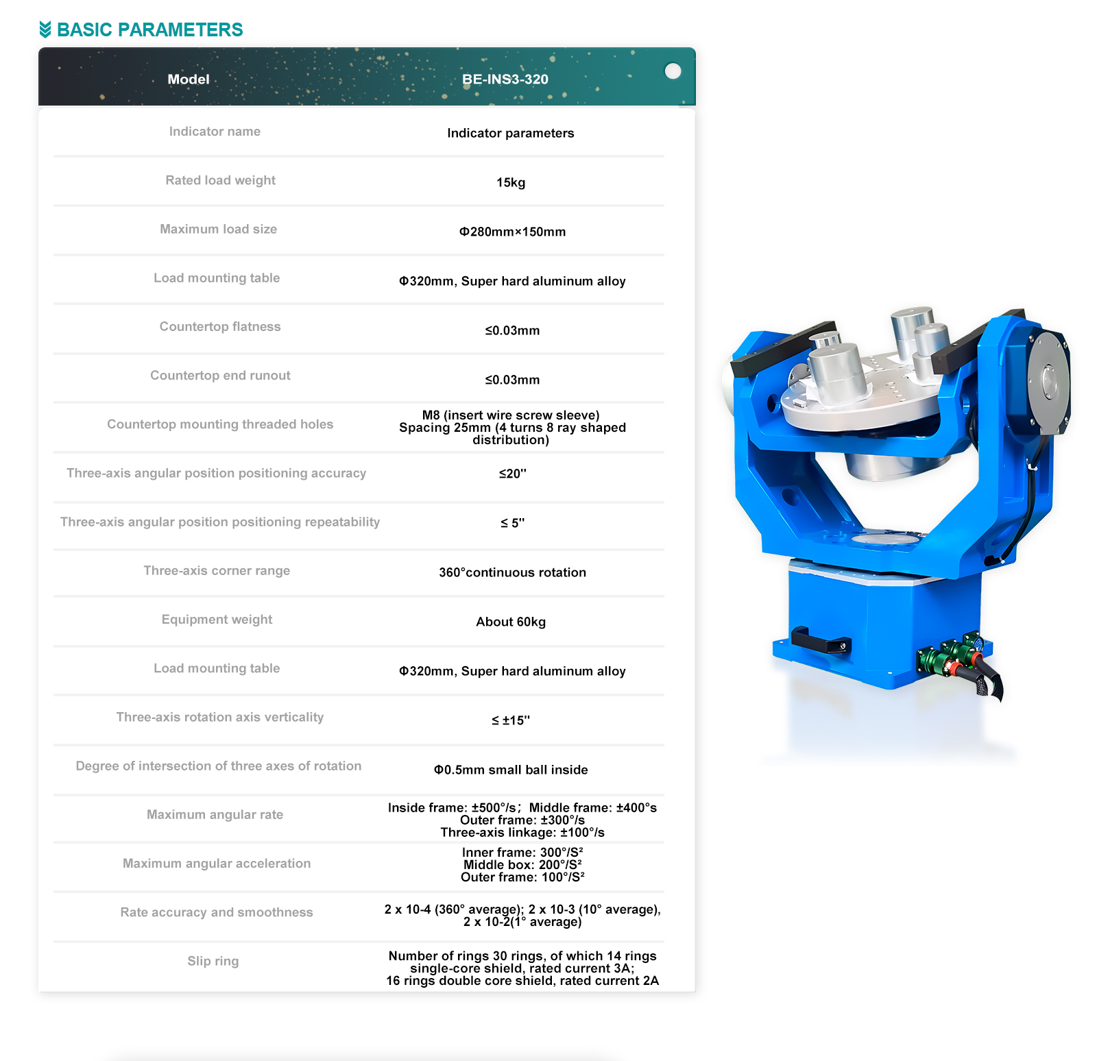
——Technical parameter——

Indicator name  

Indicator parameters

Rated load weight

15kg

Maximum load size

Ф280mm×150mm

Load mounting table 

Φ320mm, Super hard aluminum alloy

Countertop flatness

0.03mm

Countertop end runout

0.03mm

Countertop mounting threaded holes


M8 (insert wire screw sleeve) Spacing 25mm (4 turns 8 ray shaped distribution)

Three-axis angular position positioning accuracy 

20"

Triaxial Angle position positioning repeatability 

 5"

Three-axis corner range 

360°continuous rotation

Equipment weight 

About 60kg

Load mounting table 

Φ320mm, Super hard aluminum alloy

Triaxial rotation axis perpendicularity 

≤ ±15"

Degree of intersection of three axes of rotation

Φ0.5mm small ball inside

Maximum angular rate  

Inside frame: ±500°/s; Middle frame: ±400°s, Outer frame: ±300°/s; Three-axis linkage: ±100°/s

Maximum angular acceleration 

Inner frame: 300°/S², Middle box: 200°/S², Outer frame: 100°/S²

Rate accuracy and smoothness 

2 x 10⁻⁴ (360° average); 2 x 10⁻³ (10° average), 2 x 10⁻²(1° average)

Slip ring  

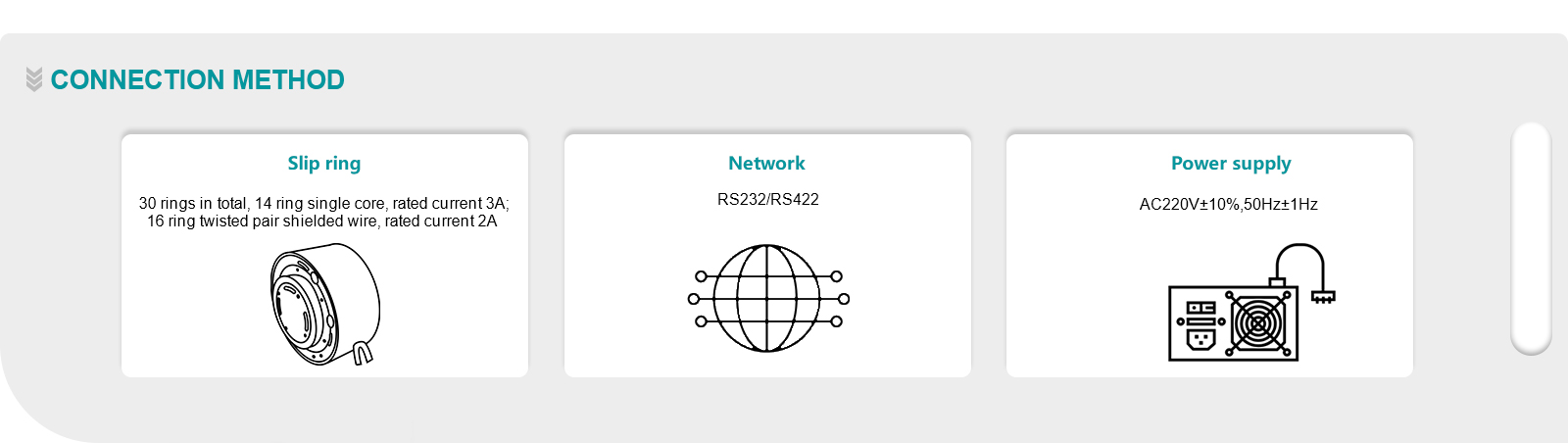
Number of rings 30 rings, of which 14 rings single-core shield, rated current 3A;  16 rings double core shield, rated current 2A